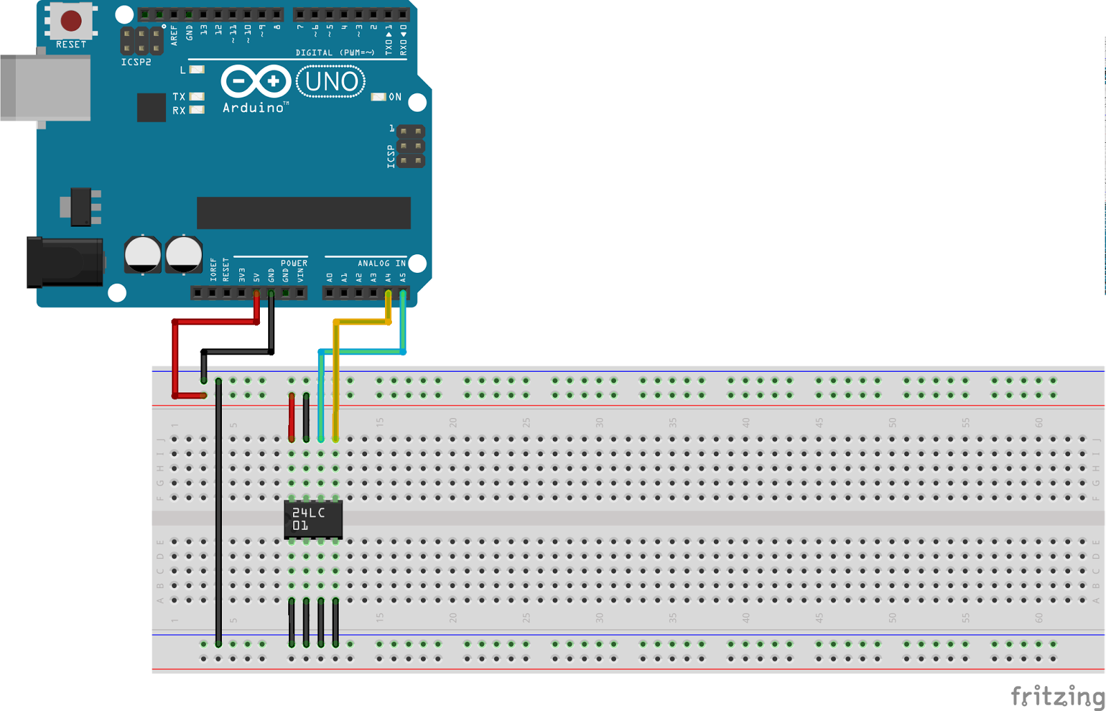
Internal EEPROM is used with the built-in library.
However:
External EEPROM (EE) has some details:
1. The pin layout is usually like this:
Things to know:
a. If this EEPROM is the only EEPROM in the project then A0, A1, A2, GND and WP pins are connected to ground. VCC pin is 5V, SCL (clock) (pin 6) to arduino pin A5, SDA (data) (pin 5) to arduino pin A4.
b. i2c protocol is being used, wire.h library handles this protocol
c. Device address is 7 bit (8th bit is not used), since A2 A1 and A0 is zero (grounded), the address becomes 1010000 or 80 or 0x50.
2. If the EEPROM size is larger than 256 byte, more than one byte is needed to address the memory
3. If data size is larger or equal to integer, more than one byte is needed to store data. In this case, disassembling and assembling of data into separate bytes is needed.
Monday, June 23, 2014
Friday, June 20, 2014
Arduino and Servo Motor (Tower Pro SG 5010)
Hardware List:
1. Arduino and breadboard
2. A servo motor like this:
3. 10k ohm potentiometer
Wiring Details:
1. Output from 10k pot to arduino analog A0
2. The step motor's yellow wire to arduino digital out pwm ~9
Use the "Servo.h" library, create a Servo object. Attach object to ~9.
Read pot, map to 180 degrees and write to this object.
Motor can move 180 degrees. Not a full circle.
Thursday, June 19, 2014
Arduino and DC Motor with Transistor and Diode
Component List:
1. A DC Motor (not servo)
2. BC547 Transistor
3. 1N4007 Diode
4. 10k ohm potentiometer
5. 1k ohm resistor
6. 9V Battery for the external powering of motor
Wiring Diagram:
Notes:
1. The diode is like a valve and used in order to avoid the flow from the motor to arduino
2. This is a NPN transistor. The left and right pins are connected to ground. Middle pin is connected to port ~11 of arduino
3. The motor can be 9V, 24V or more. By using transistor family components we can control them with our 5VDC controller.
1. A DC Motor (not servo)
2. BC547 Transistor
3. 1N4007 Diode
4. 10k ohm potentiometer
5. 1k ohm resistor
6. 9V Battery for the external powering of motor
Wiring Diagram:
1. The diode is like a valve and used in order to avoid the flow from the motor to arduino
2. This is a NPN transistor. The left and right pins are connected to ground. Middle pin is connected to port ~11 of arduino
3. The motor can be 9V, 24V or more. By using transistor family components we can control them with our 5VDC controller.
Tuesday, June 17, 2014
Arduino Uno and HC-SR04 Ultrasonic Proximity Sensor
This is an ultrasonic sensor: sends sound waves, receives echoes and calculates the time between sending and receiving. Like a bat.
Sensor is like this:
Leftmost pin is 5VDC
Second pin is Trig(ger)
Third is Echo
Last one is GND
Usage is simple: Set trig high and echo will set itself high. Get the time between (microseconds) by Arduino's pulseIn() function.
Wiring Details
Connect power pins 5VDC and GND as usual.
Connect trig to 7 as output
Connect echo to 8 as input
distance = duration/58.2 (centimeters - max distance is 200)
Sensor is like this:
HC-SR04
Leftmost pin is 5VDC
Second pin is Trig(ger)
Third is Echo
Last one is GND
Usage is simple: Set trig high and echo will set itself high. Get the time between (microseconds) by Arduino's pulseIn() function.
Wiring Details
Connect power pins 5VDC and GND as usual.
Connect trig to 7 as output
Connect echo to 8 as input
distance = duration/58.2 (centimeters - max distance is 200)
Monday, June 16, 2014
Arduino Uno and GPS GY-NEO6MV2
SW:
1. Arduino IDE
2. TinyGPS Library @ http://arduiniana.org/libraries/tinygpsplus/
4. Extra components:
4.a. 1 x 10k ohm resistor
4.b. 1 x 4.7k ohm resistor
1. Arduino IDE
2. TinyGPS Library @ http://arduiniana.org/libraries/tinygpsplus/
2.a. using "DeviceExample" example sketch
2.b. Line 9, GPS baud should be changed to 9600
3. Wiring details
image from: http://arduinostuff.blogspot.fi/
4. Extra components:
4.a. 1 x 10k ohm resistor
4.b. 1 x 4.7k ohm resistor
Subscribe to:
Comments (Atom)


